
RR-50 Rectifier Repair Kit for Small Chargers with 2 - 50A Diodes
RR-50 Rectifier Repair Kit for Small Chargers with 2 - 50A Diodes
A cost-effective solution for the repair of small charger rectifiers when an OEM replacement is cost prohibitive or unavailable. Includes illustrated installation instructions and all hardware necessary to install on the charger’s existing heat sink. Designed for use on chargers with up to 20 amp continuous output rating and/or boost capability. Multiple RR-50 kits may be used to repair rectifiers originally equipped with 4 or more button diodes.
Kit Includes
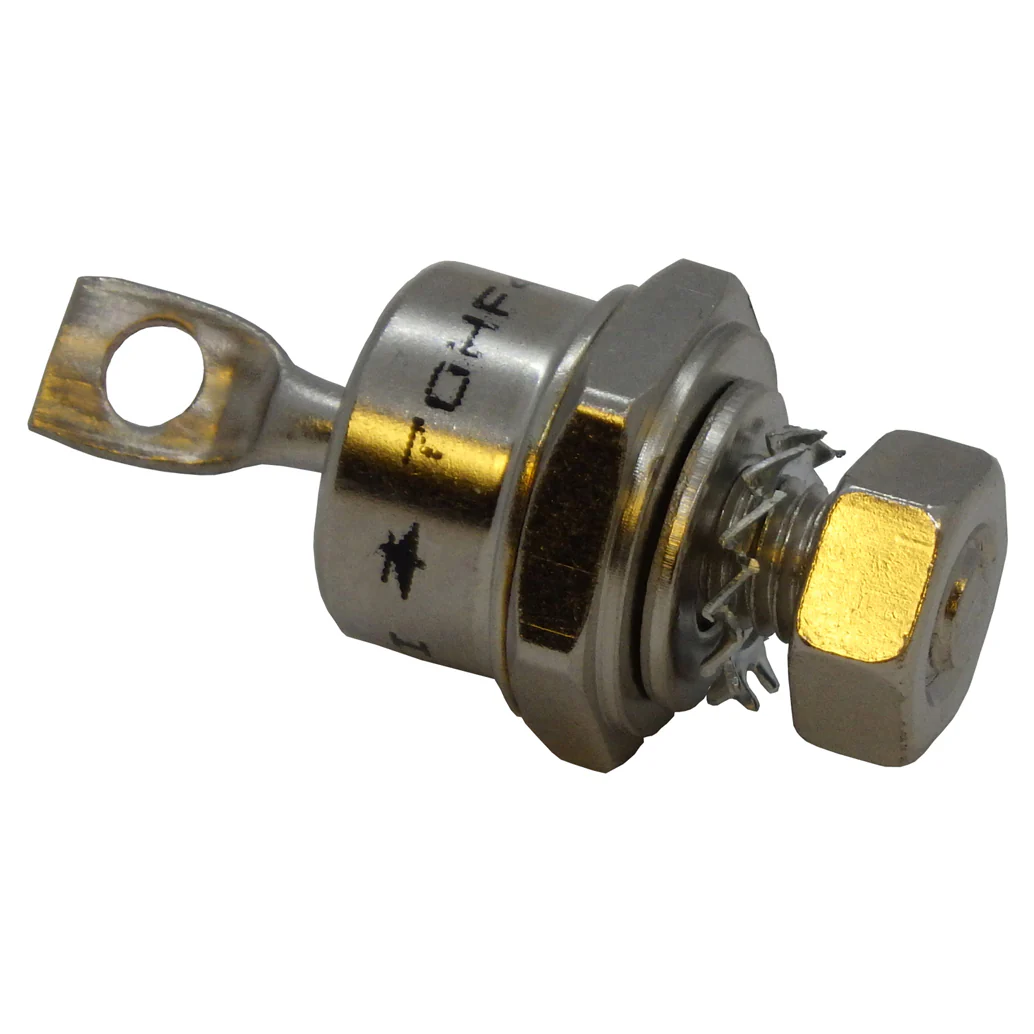
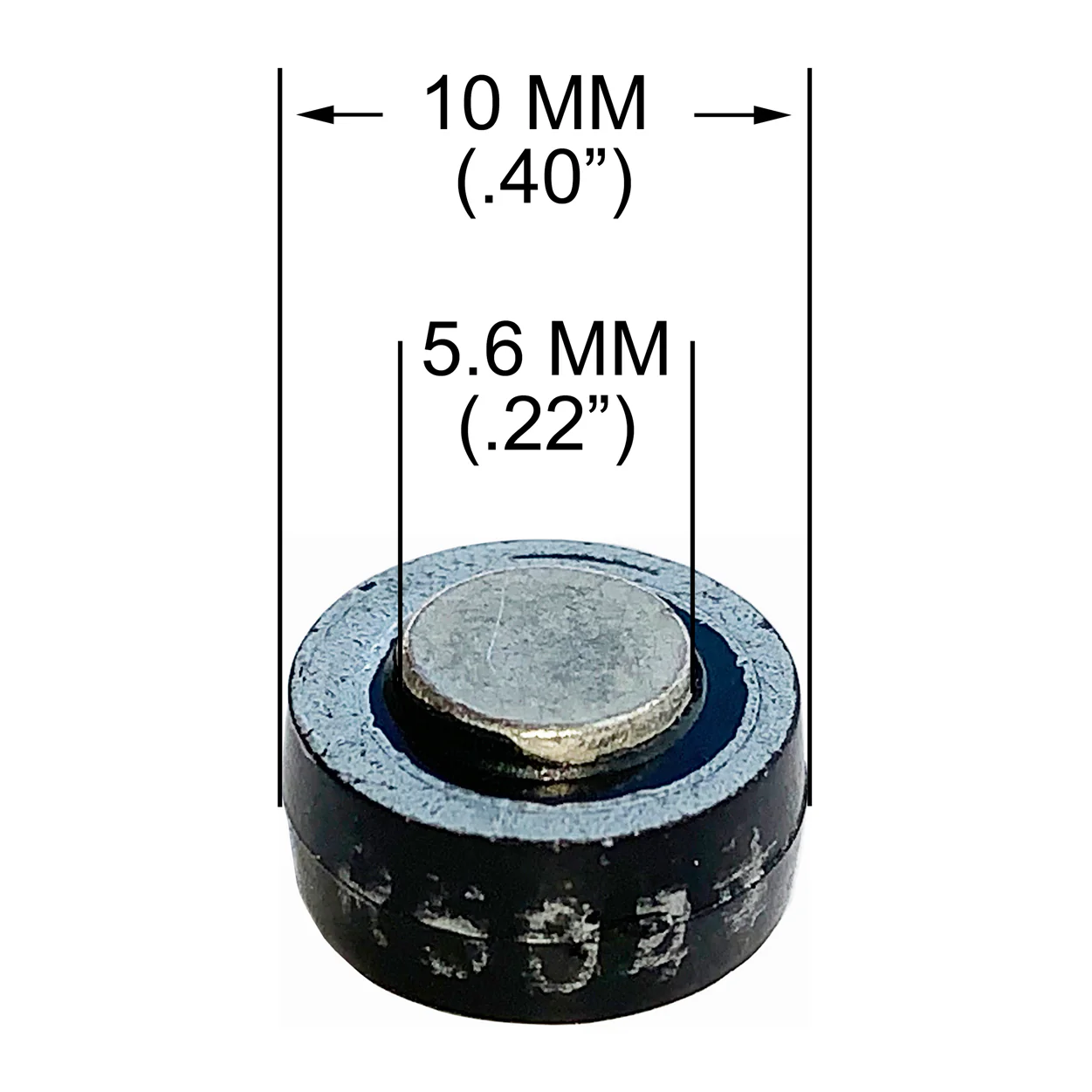
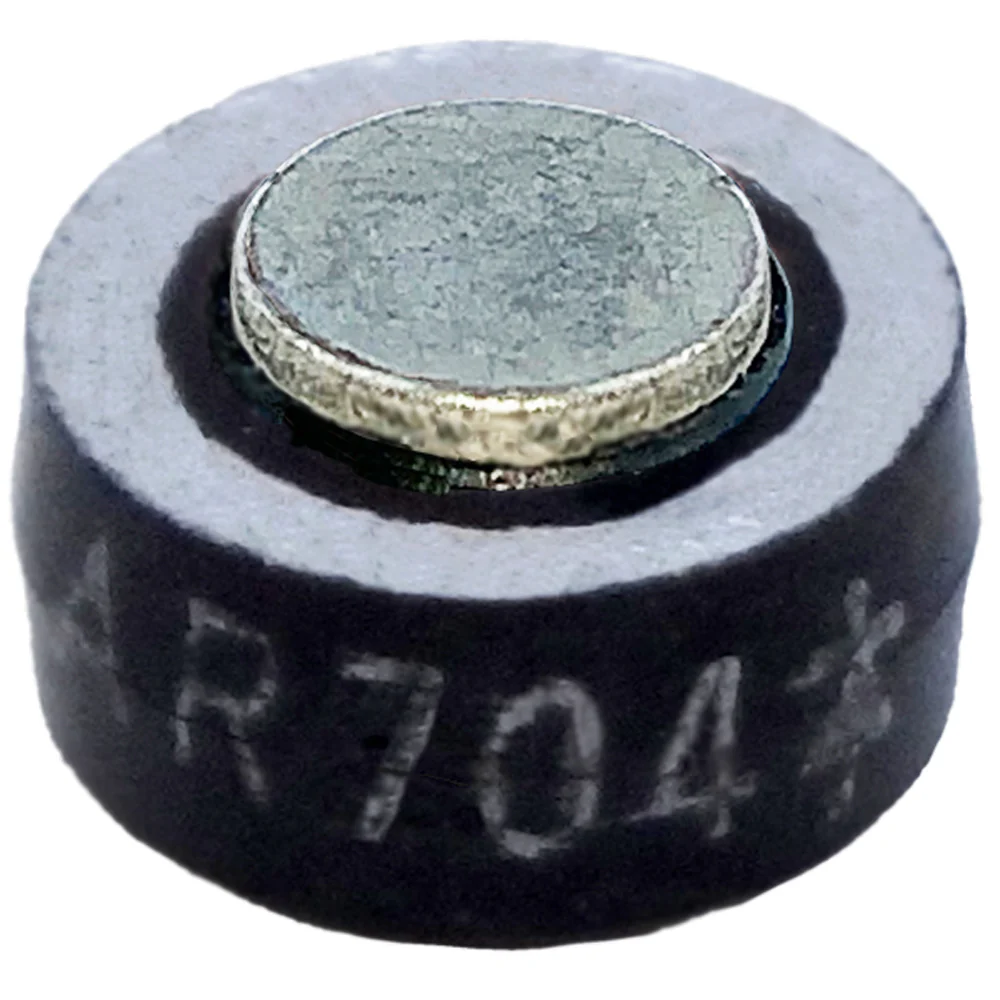
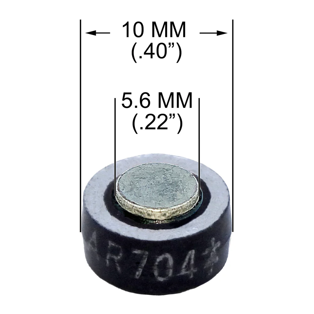
2-50A button diodes
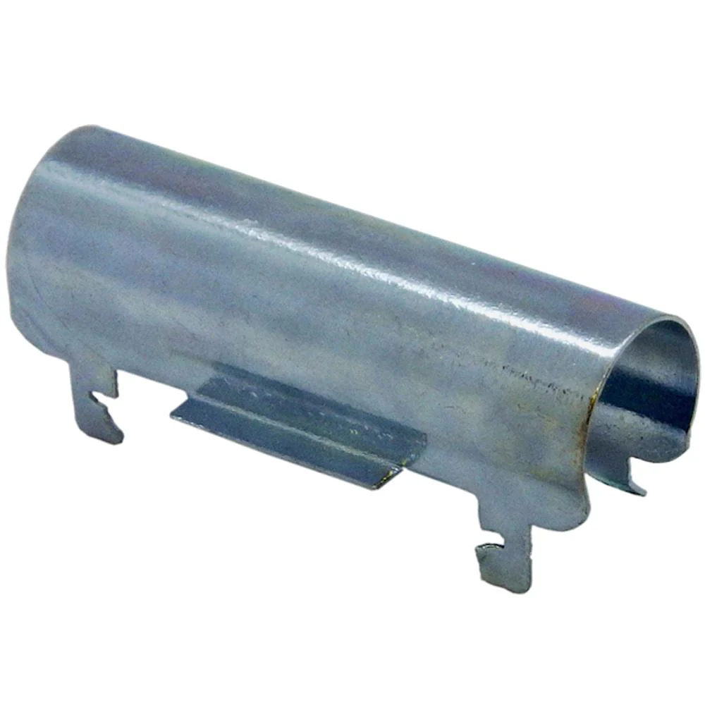
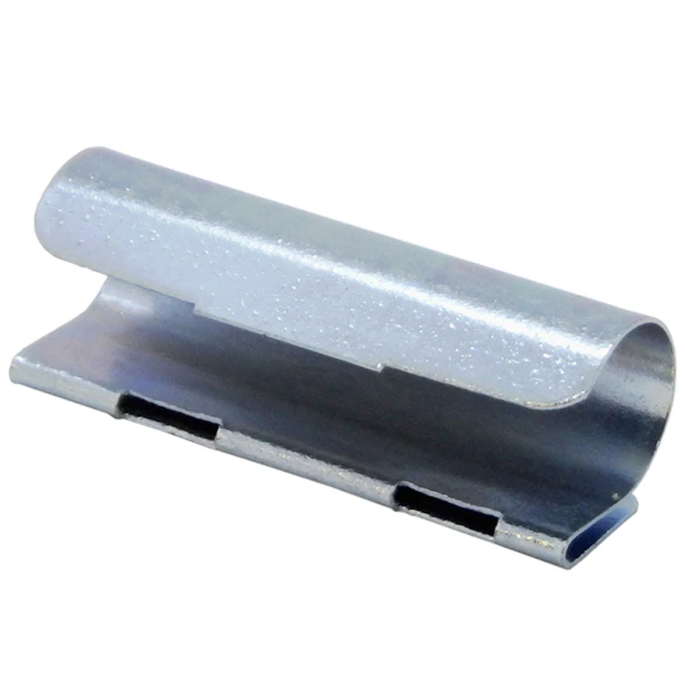
Diode retainer
Brass push-on connector tabs
Mounting hardware
Thermal Grease
Installation Instructions
Assembly
1. Use an existing hole in the heat sink, or drill a 5/32" mounting hole in the heat sink. Make sure that there at least 3/8" clearance behind the heat sink to accommodate the mounting bolt and nut.
2. Clean the heat sink mounting area by removing any dirt, grease or other debris.
3. Assemble the RR-50 as shown. The brass tabs lay in the diode retainer, and are held firmly in place by the button diodes. Make certain that the cathode contacts of both diodes are facing the same direction. (SEE POLARITY NOTE)
4. Attach assembled RR-50 to the heat sink plate.
NOTE: The RR-50 diode housing has a small plastic alignment pin on the underside. If your heat sink plate does not have a hole to accommodate this pin, simply trim it off with a sharp knife.
4. Tighten the mounting bolt/nut.
5. Attach the transformer secondary leads to the brass tabs and test the charger for proper function.
Polarity Note
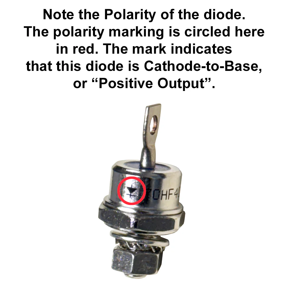
- The cathode side of the button diode is marked by a painted ring around the button contact. The anode contact is not marked. Note the position of the diodes you are replacing and install the RR-50 diodes facing the same direction.
- Most chargers are a "Positive Output" design (the DC output lead that is connected to the rectifier heat sink plate is attached to the positive battery clamp.) On these chargers, the painted rings on the diodes will face "down", against the heat sink surface. To determine if this is the proper orientation for your charger, locate the DC output wire that attaches to the rectifier heat sink plate. Follow this wire to the battery charging clamp. If the wire is attached to the Positive (+) battery clamp, then the diode cathode contacts should be faced "down" against the heat sink plate. If the wire is connected to the Negative (-) battery clamp, the diode cathode should be faced away from the heat sink plate.
RR-50 Rectifier Repair Kit for Small Chargers with 2 - 50A Diodes
A cost-effective solution for the repair of small charger rectifiers when an OEM replacement is cost prohibitive or unavailable. Includes illustrated installation instructions and all hardware necessary to install on the charger’s existing heat sink. Designed for use on chargers with up to 20 amp continuous output rating and/or boost capability. Multiple RR-50 kits may be used to repair rectifiers originally equipped with 4 or more button diodes.
Kit Includes
2-50A button diodes
Diode retainer
Brass push-on connector tabs
Mounting hardware
Thermal Grease
Installation Instructions
Assembly
1. Use an existing hole in the heat sink, or drill a 5/32" mounting hole in the heat sink. Make sure that there at least 3/8" clearance behind the heat sink to accommodate the mounting bolt and nut.
2. Clean the heat sink mounting area by removing any dirt, grease or other debris.
3. Assemble the RR-50 as shown. The brass tabs lay in the diode retainer, and are held firmly in place by the button diodes. Make certain that the cathode contacts of both diodes are facing the same direction. (SEE POLARITY NOTE)
4. Attach assembled RR-50 to the heat sink plate.
NOTE: The RR-50 diode housing has a small plastic alignment pin on the underside. If your heat sink plate does not have a hole to accommodate this pin, simply trim it off with a sharp knife.
4. Tighten the mounting bolt/nut.
5. Attach the transformer secondary leads to the brass tabs and test the charger for proper function.
Polarity Note
- The cathode side of the button diode is marked by a painted ring around the button contact. The anode contact is not marked. Note the position of the diodes you are replacing and install the RR-50 diodes facing the same direction.
- Most chargers are a "Positive Output" design (the DC output lead that is connected to the rectifier heat sink plate is attached to the positive battery clamp.) On these chargers, the painted rings on the diodes will face "down", against the heat sink surface. To determine if this is the proper orientation for your charger, locate the DC output wire that attaches to the rectifier heat sink plate. Follow this wire to the battery charging clamp. If the wire is attached to the Positive (+) battery clamp, then the diode cathode contacts should be faced "down" against the heat sink plate. If the wire is connected to the Negative (-) battery clamp, the diode cathode should be faced away from the heat sink plate.
Description
RR-50 Rectifier Repair Kit for Small Chargers with 2 - 50A Diodes
A cost-effective solution for the repair of small charger rectifiers when an OEM replacement is cost prohibitive or unavailable. Includes illustrated installation instructions and all hardware necessary to install on the charger’s existing heat sink. Designed for use on chargers with up to 20 amp continuous output rating and/or boost capability. Multiple RR-50 kits may be used to repair rectifiers originally equipped with 4 or more button diodes.
Kit Includes
2-50A button diodes
Diode retainer
Brass push-on connector tabs
Mounting hardware
Thermal Grease
Installation Instructions
Assembly
1. Use an existing hole in the heat sink, or drill a 5/32" mounting hole in the heat sink. Make sure that there at least 3/8" clearance behind the heat sink to accommodate the mounting bolt and nut.
2. Clean the heat sink mounting area by removing any dirt, grease or other debris.
3. Assemble the RR-50 as shown. The brass tabs lay in the diode retainer, and are held firmly in place by the button diodes. Make certain that the cathode contacts of both diodes are facing the same direction. (SEE POLARITY NOTE)
4. Attach assembled RR-50 to the heat sink plate.
NOTE: The RR-50 diode housing has a small plastic alignment pin on the underside. If your heat sink plate does not have a hole to accommodate this pin, simply trim it off with a sharp knife.
4. Tighten the mounting bolt/nut.
5. Attach the transformer secondary leads to the brass tabs and test the charger for proper function.
Polarity Note
- The cathode side of the button diode is marked by a painted ring around the button contact. The anode contact is not marked. Note the position of the diodes you are replacing and install the RR-50 diodes facing the same direction.
- Most chargers are a "Positive Output" design (the DC output lead that is connected to the rectifier heat sink plate is attached to the positive battery clamp.) On these chargers, the painted rings on the diodes will face "down", against the heat sink surface. To determine if this is the proper orientation for your charger, locate the DC output wire that attaches to the rectifier heat sink plate. Follow this wire to the battery charging clamp. If the wire is attached to the Positive (+) battery clamp, then the diode cathode contacts should be faced "down" against the heat sink plate. If the wire is connected to the Negative (-) battery clamp, the diode cathode should be faced away from the heat sink plate.